
Event trigger interval data output
Purpose
Section titled “Purpose”Save only the data during intervals when a specific event is occurring as CSV files, enabling efficient use of the necessary data.
Project files
Section titled “Project files”These are the project files used in this example. A standard version and a version with the PLC Collector configured in simulation mode are available.
Note: Import requires SpeeDBee Synapse version 4.9.9 or later.
What you will learn
Section titled “What you will learn”- How to retain only data captured while a specific event is occurring
- How to extract only the required intervals rather than recording continuously
- How to use PLC signals as triggers to control recording start and end
Requirements
Section titled “Requirements”The following data is being collected from a PLC, and the data from when signal turns ON (=1) to when it turns OFF (=0) is to be saved as a CSV file.
- signal
- temperature
- humidity
Components used
Section titled “Components used”- PLC Collector (data collection)
- Event trigger (start/end condition evaluation)
- CSV Serializer (converts received data to CSV)
- File Emitter (saves CSV data as a file)
Workflow
Section titled “Workflow”- Collect signal, temperature, and humidity data with the PLC Collector
- Use the Event trigger to evaluate start/end conditions based on the signal value
- Use the CSV Serializer to generate data for that interval based on the Event trigger’s start/end conditions
- Use the File Emitter to save the data from the CSV Serializer as a file
-
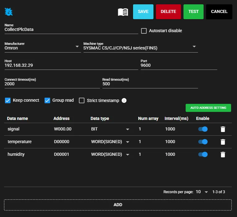
Configure the PLC Collector. Specify the PLC connection target, data to collect, and save the settings.
-
Next, configure the Event trigger. When registering a new Event trigger, a dialog appears to select the component to connect to the input port. Select the PLC Collector and click CONNECT.
Note: The PLC Collector must be running before it can be selected — start it beforehand. It can also be started using the ▶ button.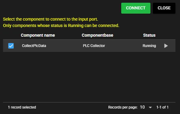
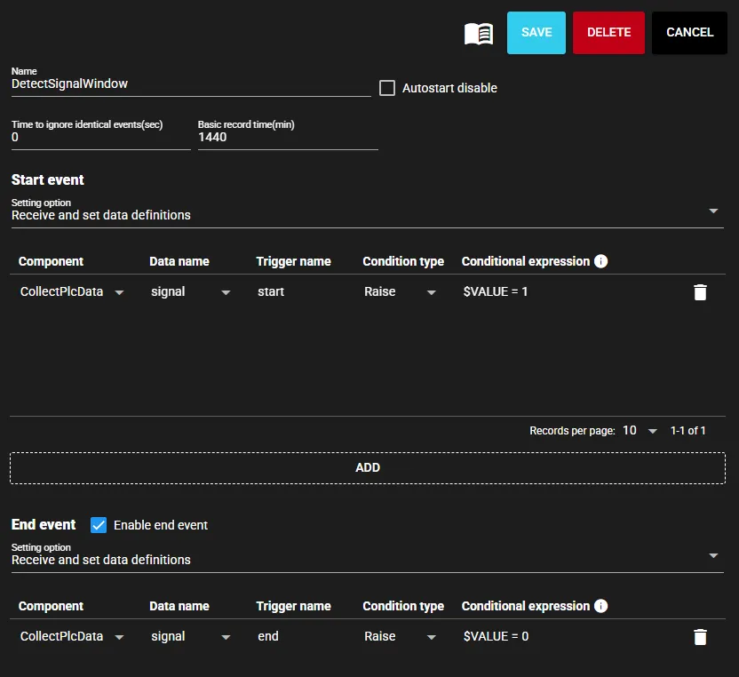
After connecting, specify the start event, end event conditions, and other settings in the Event trigger, then save.
-
Configure the CSV Serializer.
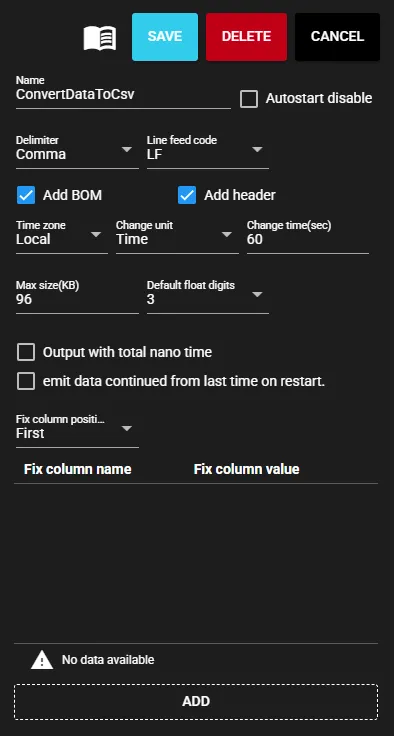
After saving the settings, connect the PLC Collector to the CSV Serializer and the Event trigger to the CSV Serializer using flow links.
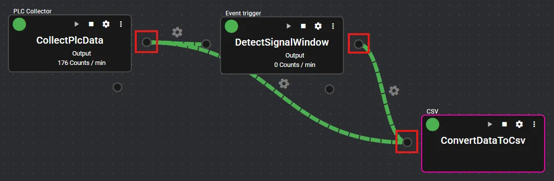
Next, right-click the input port of the CSV Serializer and open the input port settings. Check Use event, select the Event trigger configured in step 2, and save.
Note: The Use event setting cannot be configured unless the Event trigger is running — start it beforehand.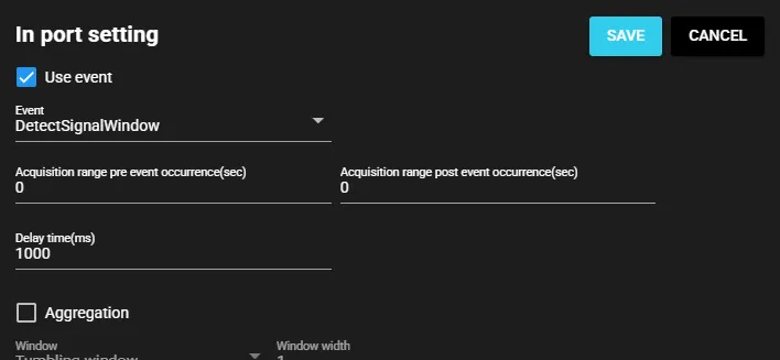
-
Finally, configure the File Emitter.
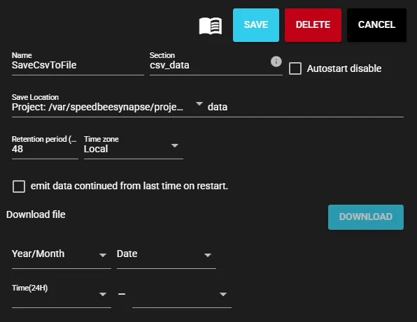
After saving the settings, connect the CSV Serializer and the File Emitter using a flow link.
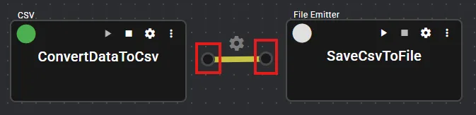
-
Start each component.
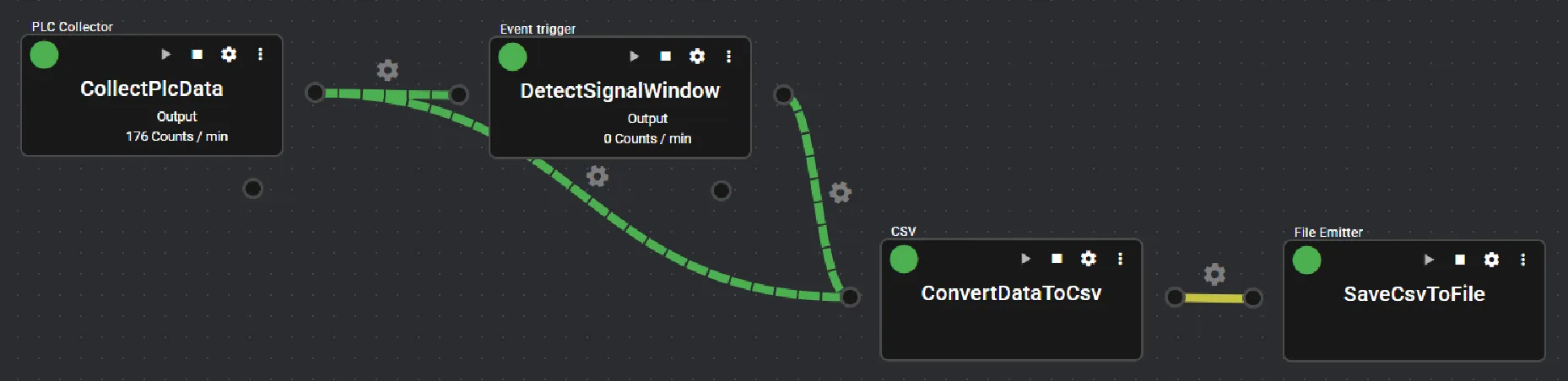
Checking output files
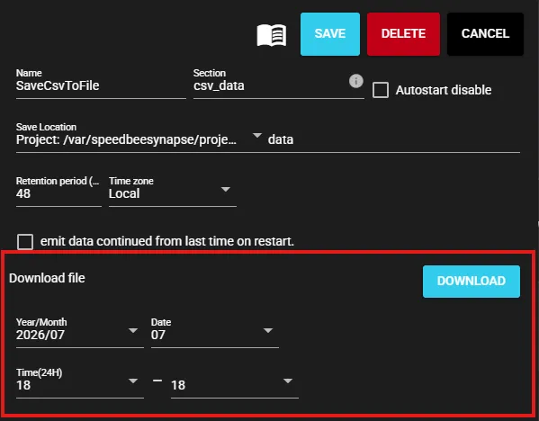
Section titled “Checking output files”From the File Emitter settings screen, you can download files saved within a specified time range. The downloaded files are in ZIP format — extract them before use.
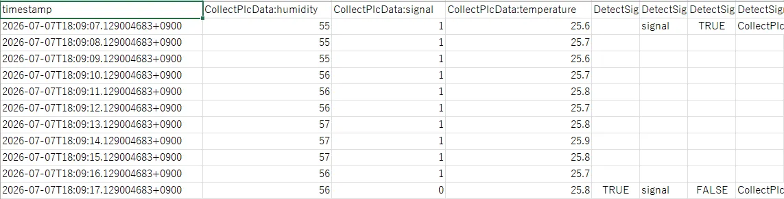
The downloaded CSV contains data as shown below, and you can see that the data has been extracted from when signal=1 until signal=0.
Sample downloaded CSV file
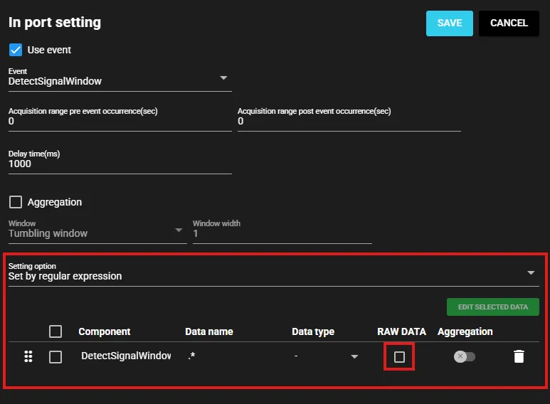
Data from the Event trigger (DetectSignalWindow) is also included in the CSV output. If not needed, you can exclude it from the CSV by specifying the target data (in this case, all DetectSignalWindow data) in the CSV Serializer’s input port settings and turning RAW DATA OFF.
CSV Serializer file changing
Section titled “CSV Serializer file changing”By design, when the CSV Serializer is used with events as in this example, it generally outputs the data from event start to end as a single CSV file. However, depending on the timing of events and the changing settings (change time, change count, change window count), files may be split.
For example, with a change time of 60 seconds, if the interval from event start to end takes 100 seconds, a file will be output once at the 60-second change time, and the remaining data will be output to a separate file when the end event occurs. To avoid splitting, the change time should be set to a larger value. In this example, setting the change time to around 110 seconds would allow the entire interval to be output as a single file, as long as the start-to-end duration stays within 110 seconds.
Note: As of the current date (2026-07-14), the maximum change time is 3600 seconds (1 hour).